
Page 273 - Robot Builder's Bonanza
P. 273
242 USING DC MOTORS
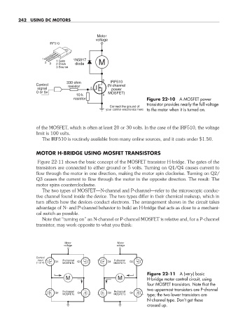
Motor
voltage
IRF510
1 1N5817
2 3 1 Gate diode M
2 Drain
3 Source
D
330 ohm IRF510
Control resistor (N-channel
signal G power
0 or 5v MOSFET)
10 k S
resistor Figure 22- 10 A MOSFET power
transistor provides nearly the full voltage
Connect the ground of
your control electronics here to the motor when it is turned on.
of the MOSFET, which is often at least 20 or 30 volts. In the case of the IRF510, the voltage
limit is 100 volts.
The IRF510 is routinely available from many online sources, and it costs under $1.50.
MOTOR H- BRIDGE USING MOSFET TRANSISTORS
Figure 22- 11 shows the basic concept of the MOSFET transistor H- bridge. The gates of the
transistors are connected to either ground or 5 volts. Turning on Q1/Q4 causes current to
flow through the motor in one direction, making the motor spin clockwise. Turning on Q2/
Q3 causes the current to flow through the motor in the opposite direction. The result: The
motor spins counterclockwise.
The two types of MOSFET— N- channel and P- channel— refer to the microscopic conduc-
tive channel found inside the device. The two types differ in their chemical makeup, which in
turn affects how the devices conduct electrons. The arrangement shown in the circuit takes
advantage of N- and P- channel behavior to build an H- bridge that acts as close to a mechani-
cal switch as possible.
Note that “turning on” an N- channel or P- channel MOSFET is relative and, for a P- channel
transistor, may work opposite to what you think:
Motor Motor
voltage voltage
Control
input P-channel P-channel
(1 of 4) Q1 MOSFETs Q3 Q1 MOSFETs Q3
Figure 22- 11 A (very) basic
M M H- bridge motor control circuit, using
four MOSFET transistors. Note that the
two uppermost transistors are P- channel
N-channel N-channel
Q2 Q4 Q2 Q4
MOSFETs MOSFETs type; the two lower transistors are
N- channel type. Don’t get these
crossed up.
22-chapter-22.indd 242 4/21/11 11:50 AM