
Page 271 - Robot Builder's Bonanza
P. 271
240 USING DC MOTORS
Motor
voltage
TIP31/TIP32
1N5817
1 1 Base
2 3 2 Collector M diode
3 Emitter
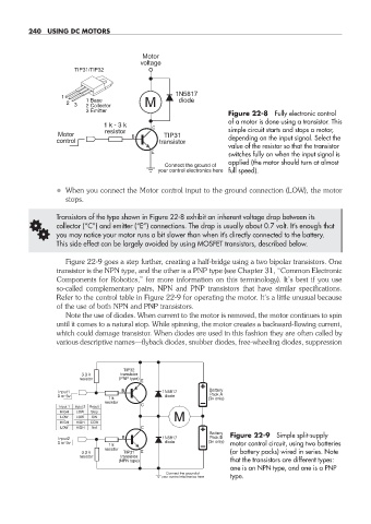
Figure 22- 8 Fully electronic control
of a motor is done using a transistor. This
1 k - 3 k
resistor simple circuit starts and stops a motor,
Motor TIP31
control transistor depending on the input signal. Select the
value of the resistor so that the transistor
switches fully on when the input signal is
applied (the motor should turn at almost
Connect the ground of
your control electronics here full speed).
• When you connect the Motor control input to the ground connection (LOW), the motor
stops.
Transistors of the type shown in Figure 22- 8 exhibit an inherent voltage drop between its
G collector (“C”) and emitter (“E”) connections. The drop is usually about 0.7 volt. It’s enough that
you may notice your motor runs a bit slower than when it’s directly connected to the battery.
This side effect can be largely avoided by using MOSFET transistors, described below.
Figure 22- 9 goes a step further, creating a half- bridge using a two bipolar transistors. One
transistor is the NPN type, and the other is a PNP type (see Chapter 31, “Common Electronic
Components for Robotics,” for more information on this terminology). It’s best if you use
so- called complementary pairs, NPN and PNP transistors that have similar specifications.
Refer to the control table in Figure 22- 9 for operating the motor. It’s a little unusual because
of the use of both NPN and PNP transistors.
Note the use of diodes. When current to the motor is removed, the motor continues to spin
until it comes to a natural stop. While spinning, the motor creates a backward- flowing current,
which could damage transistor. When diodes are used in this fashion they are often called by
various descriptive names— flyback diodes, snubber diodes, free- wheeling diodes, suppression
TIP32
3.3 k transistor
resistor (PNP type)
Input1 1N5817 Battery
Pack A
0 or 5v 1 k diode (3v only)
resistor
esu
nput 2
I
I
Input 1nput 1 Input 2 R Result lt
HIGH
HIGH LOW Stop
LOW
Stop
LOW
LOW
LOW LOW CW M
HIGH
HIGH
HIGH HIGH CCW
LOW
LOW HIGH No!
HIGH
Battery Figure 22- 9 Simple split- supply
Input2 1N5817 Pack B
0 or 5v diode (3v only) motor control circuit, using two batteries
1 k
resistor
3.3 k TIP31 (or battery packs) wired in series. Note
resistor transistor
(NPN type) that the transistors are different types:
one is an NPN type, and one is a PNP
Connect the ground of
your control electronics here type.
22-chapter-22.indd 240 4/21/11 11:50 AM