
Page 276 - Robot Builder's Bonanza
P. 276
MOTOR CONTROL BY BRIDGE MODULE 245
• The L293D can supply up to 600 mA of current (continuous, per channel).
• The 754410 can supply up to 1.1 A of current (continuous, per channel).
On both chips, the supply voltage ranges from 4.5 to 36 volts, and they have connections for
not just one motor but two.
From here on out I’ll refer just to the L293D, but know the discussion applies to the
754410 as well.
When buying the L293D, be sure it has a D at the end of it. “D” denotes diodes. Recall the use
of diodes used to protect components in the transistorized H- bridges described earlier in this
chapter. The L293D (and the 754410) have these diodes built in. If you don’t get the D version
of the L293, you’ll need to add these diodes yourself.
G about whether the diodes built into the 754410 are intended for flyback protection. The
While we’re on the subject of diodes: There is some disagreement among robo- builders
datasheet for the 754410 is not clear on the subject. Adding to the confusion is that several
versions of the datasheet contain other errors. If you want to be sure that the 754410 is fully
protected, you can add external diodes, such as 1N5817. But if playing safe is the key, this
suggestion applies equally to the L293D and any other motor bridge IC.
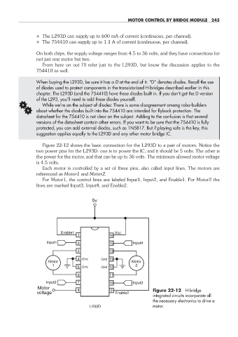
Figure 22- 12 shows the basic connection for the L293D to a pair of motors. Notice the
two power pins for the L293D: one is to power the IC, and it should be 5 volts. The other is
the power for the motor, and that can be up to 36 volts. The minimum allowed motor voltage
is 4.5 volts.
Each motor is controlled by a set of three pins, also called input lines. The motors are
referenced as Motor1 and Motor2.
For Motor1, the control lines are labeled Input1, Input2, and Enable1. For Motor2 the
lines are marked Input3, Input4, and Enable2.
5v
Enable1 Vcc
1 16
Input1 2 15 Input4
3 13
4 Gnd Gnd 13
Motor Motor
1 2
5 Gnd Gnd 12
6 11
Input2 7 10 Input3
Motor 8 9 Figure 22- 12 H- bridge
voltage Enable2
integrated circuits incorporate all
the necessary electronics to drive a
L293D motor.
22-chapter-22.indd 245 4/21/11 11:50 AM