
Page 274 - Robot Builder's Bonanza
P. 274
MOTOR CONTROL BY POWER MOSFET TRANSISTOR 243
Gate Signal N- channel P- channel
0 volts (LOW, logical 0) Turns off Turns on
5 volts (HIGH, logical 1) Turns on Turns off
Unlike bipolar transistors, which exhibit a drop in voltage when current is passed through
them, MOSFET transistors pass through nearly all of the volts to the motor.
The N- and P- channel MOSFET transistors you use should be complementary pairs, that is,
transistors that share similar specifications. This provides a balance in current- carrying
capability. For example, you might use IRF530/IRF9530 or IRF540/IRF9540. Not all MOSFETs
G use such convenient numbering sequences to indicate pairing. You can consult a basic data
book to find complementary pairs, and be sure to read the specifications provided by online
retailers. Most retailers provide direct links to datasheets provided by the MOSFET
manufacturers, and you’re encouraged to review them and compare specifications.
There are many ways to build MOSFET H- bridges, and each method has its distinct advantages.
Rather than trying to cover them here— which wouldn’t do them justice— see the bonus H- bridge
ON THE
projects on the RBB Online Support site (refer to Appendix A for details). Included are several
W E B
tested variations, from fairly simple to somewhat complex.
COMMON DESIGN GOALS FOR TRANSISTOR H- BRIDGES
If you’d like to design your own MOSFET transistor H- bridge, keep these basic design goals
in mind.
First, the transistors you choose must be capable of handing the current draw demanded
by the motor. Refer to the motor specifications to determine their maximum current draw, or
test it yourself using the steps in Chapter 21, “Choosing the Right Motor.”
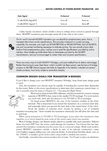
Most motors draw at least 500 milliamps, and this exceeds the current- carrying
TO-92 capacity of MOSFETs that come in the smaller TO- 92 package. For most motors
you work with, stick with the devices in the TO- 220 or TO- 3 packages.
TO-220
Shown On larger- power MOSFETs, the case of the transistor doubles as the drain
approximate
scale terminal. This is important if you mount the transistors on a common heat sink,
TO-3 and especially when you ground the heat sink to the metal frame of the robot.
Avoid the hassles of potential short circuits by getting a set of insulated
transistor- mounting kits. These insulate the transistors electrically but still allow the heat sink
to sink heat.
When using transistors in TO- 220 or TO- 3 packages, if you place the transistors close
together on a circuit board be sure none of the metal cases touch one another.
Most H- bridge designs use flyback diodes placed in parallel with each transistor. Without
these, the back EMF from the motor could damage the transistor. You’ll know this has hap-
pened if the transistor constantly runs the motor, but at a reduced voltage. While most modern
power MOSFET transistors include a diode as part of its internal construction, many
robo- builders suggest adding your own external diodes. A fast- acting Schottky diode, such as
the 1N5817, is usually a good choice when using small to medium-size motors.
And finally, remember that motors produce lots of noise. You’ll want to place an aluminum
22-chapter-22.indd 243 4/21/11 11:50 AM