
Page 270 - Robot Builder's Bonanza
P. 270
MOTOR CONTROL BY BIPOLAR TRANSISTOR 239
Control 1
0 or 5v 16
2 15
3 13
Relay
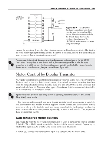
4 13 Figure 22- 7 The ULN2003
Darlington array integrated circuit
5 12
contains seven independent drive
6 11 5v circuits. These drive circuits include
the flyback diode shown in the
7 10
previous relay diagrams. The
8 ULN2003 9
ULN2003 is a simpler method when
using many relays.
can use the remaining drivers for other relays or even something else completely— like lighting
up some superbright light- emitting diodes. If a driver is not used, disable it by connecting its
input to ground. Leave its output unconnected.
You may see similar circuit diagrams showing diodes used on the outputs of the ULN2003.
G That’s okay. The chip has its own diodes built in, but some designers like to take the extra
precaution and add their own. For the smallish relays typically used in hobby robots, the extra
diodes are not usually needed, but you can add them if you wish.
Motor Control by Bipolar Transistor
No, bipolar transistors don’t exhibit manic- depressive behavior. In this case, bipolar is merely
the term used to describe their internal construction— which we won’t be getting into here
since it’s not particularly relevant (besides, there are, like, 10,000 books and Web sites that
already talk all about it). There are other types of transistors, but the ones we’re interested in
for the time being are the bipolar variety.
G Bipolar transistors are more accurately known as bipolar junction transistors, or BJTs. Same
thing, slightly more words.
For robotics motor control, you use a bipolar transistor much as you would a switch. In
fact, the transistor acts just like a switch: apply or remove current, and the transistor (switch)
turns on or off. In order to do its work as a motor control switch, the transistor needs a few
extra common electronic components, specifically, a resistor and a diode. The purpose of
these are described shortly.
BASIC TRANSISTOR MOTOR CONTROL
See Figure 22- 8 for the most basic implementation of using a transistor to operate a motor.
A digital LOW or HIGH signal is applied to the input of the transistor circuit. Depending on
whether the input is LOW or HIGH, the motor turns on or it turns off.
• When you connect the Motor control input to 5 volts (HIGH), the motor turns.
22-chapter-22.indd 239 4/21/11 11:50 AM