
Page 267 - Robot Builder's Bonanza
P. 267
236 USING DC MOTORS
• Gates are inputs or outputs on a digital circuit, such as from a computer or a microcon-
troller. As you might guess, you’d use an output gate when operating a relay via a digital
circuit.
In this circuit, LOW turns the relay off and HIGH turns it on. The relay can be operated
from most any digital gate. The chapters in Part 5 deal much more extensively with using
electronic and computerized control. If you’re wanting to try relays, familiarize yourself with
the wiring diagram in Figure 22- 4. It will prepare you for these later chapters.
CONTROLLING DIRECTION VIA RELAY
Changing the direction of the motor is only a little more difficult using relays than turning it on
and off. As with the manual switches in the previous section, this requires a DPDT relay, wired
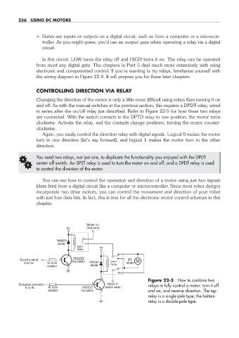
in series after the on/off relay just described. Refer to Figure 22- 5 for how these two relays
are connected. With the switch contacts in the DPTD relay in one position, the motor turns
clockwise. Activate the relay, and the contacts change positions, turning the motor counter-
clockwise.
Again, you easily control the direction relay with digital signals. Logical 0 makes the motor
turn in one direction (let’s say forward), and logical 1 makes the motor turn in the other
direction.
G You need two relays, not just one, to duplicate the functionality you enjoyed with the DPDT
center- off switch. An SPST relay is used to turn the motor on and off, and a DPDT relay is used
to control the direction of the motor.
You can see how to control the operation and direction of a motor using just two signals
(data bits) from a digital circuit like a computer or microcontroller. Since most robot designs
incorporate two drive motors, you can control the movement and direction of your robot
with just four data bits. In fact, this is true for all the electronic motor control schemes in this
chapter.
Motor V+
5v (red wire)
1N4001
diode
SPST 5v
Relay
2N2222
On/off control transistor DC M
0 or 5v 1k ohm 1N4001 DPDT motor
Relay
resistor diode
Figure 22- 5 How to combine two
Direction control Motor V- relays to fully control a motor: turn it off
0 or 5v 1k ohm 2N2222 (black wire)
resistor transistor and on, and reverse direction. The top
relay is a single- pole type; the bottom
relay is a double- pole type.
22-chapter-22.indd 236 4/21/11 11:50 AM