
Page 268 - Robot Builder's Bonanza
P. 268
MOTOR CONTROL BY RELAY 237
5v
1N4001
diode
SPST
Relay
2N2222
Direction A transistor
0 or 5v 1k ohm M
resistor
5v
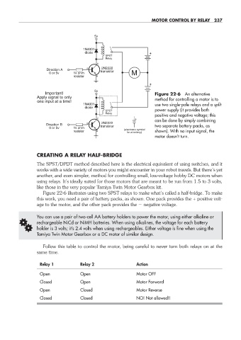
Important! Figure 22- 6 An alternative
Apply signal to only method for controlling a motor is to
one input at a time!
1N4001 use two single- pole relays and a split
diode
SPST power supply (it provides both
Relay
positive and negative voltage; this
can be done by simply combining
2N2222
Direction B transistor two separate battery packs, as
0 or 5v 1k ohm
resistor (electronic symbol shown). With no input signal, the
for a battery)
motor doesn’t turn.
CREATING A RELAY HALF- BRIDGE
The SPST/DPDT method described here is the electrical equivalent of using switches, and it
works with a wide variety of motors you might encounter in your robot travels. But there’s yet
another, and even simpler, method for controlling small, low- voltage hobby DC motors when
using relays. It’s ideally suited for those motors that are meant to be run from 1.5 to 3 volts,
like those in the very popular Tamiya Twin Motor Gearbox kit.
Figure 22- 6 illustrates using two SPST relays to make what’s called a half- bridge. To make
this work, you need a pair of battery packs, as shown. One pack provides the + positive volt-
age to the motor, and the other pack provides the negative voltage.
You can use a pair of two- cell AA battery holders to power the motor, using either alkaline or
G rechargeable NiCd or NiMH batteries. When using alkalines, the voltage for each battery
holder is 3 volts; it’s 2.4 volts when using rechargeables. Either voltage is fine when using the
Tamiya Twin Motor Gearbox or a DC motor of similar design.
Follow this table to control the motor, being careful to never turn both relays on at the
same time.
Relay 1 Relay 2 Action
Open Open Motor OFF
Closed Open Motor Forward
Open Closed Motor Reverse
Closed Closed NO! Not allowed!!
22-chapter-22.indd 237 4/21/11 11:50 AM