
Page 282 - Robot Builder's Bonanza
P. 282
CONTROL SIGNALS FOR R/C SERVOS 251
The motor and potentiometer are connected to a control board, all three of which form a
closed feedback loop. The servo is powered by 4.8 to 7.2 volts.
G You can’t run an R/C servo simply by connecting it to a battery. It needs special control signals
to operate. As it turns out, it’s not terribly hard to control a servo using simple programming.
Numerous programming examples are provided in Part 7.
LIMITING ROTATION
As you can surmise, servo motors are designed for limited rotation rather than for continuous
rotation like a DC motor. While there are servos that rotate continuously, and you can modify
one to freely rotate (see later in this chapter), the primary use of the R/C servo is to achieve
accurate rotational positioning over a range of up to 180°.
While 180°—half a circle— may not sound like much, in actuality such control can be used
to steer a robot, move legs up and down, rotate a sensor to scan the room, and more. The
precise angular rotation of a servo in response to a specific digital signal has enormous uses
in all fields of robotics.
Control Signals for R/C Servos
The control signal that commands a servo to move to a specific point is in the form of a steady
stream of electrical pulses. The exact duration of the pulses, in fractions of a millisecond
(one- thousandths of a second), determines the position of the servo, as shown in Figure 23- 3.
Note that it is not the number of pulses per second that controls the servo, but the dura-
tion of the pulses that matters. This is very important to fully understand how servos work and
how to control them with a microcontroller or other circuit.
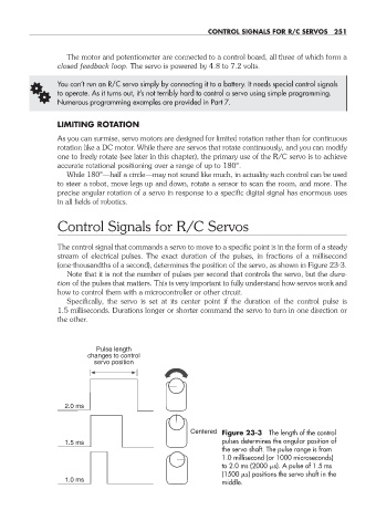
Specifically, the servo is set at its center point if the duration of the control pulse is
1.5 milliseconds. Durations longer or shorter command the servo to turn in one direction or
the other.
Pulse length
changes to control
servo position
2.0 ms
Centered Figure 23- 3 The length of the control
1.5 ms pulses determines the angular position of
the servo shaft. The pulse range is from
1.0 millisecond (or 1000 microseconds)
to 2.0 ms (2000 s). A pulse of 1.5 ms
(1500 s) positions the servo shaft in the
1.0 ms
middle.
23-chapter-23.indd 251 4/21/11 11:51 AM