
Page 321 - Robot Builder's Bonanza
P. 321
290 ROBOT MOVEMENT WITH SHAPE MEMORY ALLOY
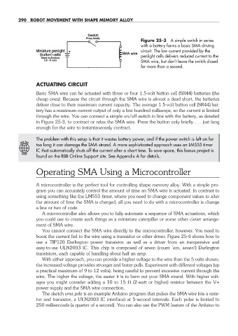
Figure 25- 3 A simple switch in series
with a battery forms a basic SMA driv ing
circuit. The low current provided by the
penlight cells delivers reduced current to the
SMA wire, but don’t leave the switch closed
for more than a second.
ACTUATING CIRCUIT
Basic SMA wire can be actuated with three or four 1.5- volt button cell (SR44) batteries (the
cheap ones). Because the circuit through the SMA wire is almost a dead short, the batteries
deliver close to their maximum current capacity. The average 1.5- volt button cell (SR44) bat-
tery has a maximum current output of only a few hundred milliamps, so the current is limited
through the wire. You can connect a simple on/off switch in line with the battery, as detailed
in Figure 25- 3, to contract or relax the SMA wire. Press the button only briefly . . . just long
enough for the wire to instantaneously contract.
The problem with this setup is that it wastes battery power, and if the power switch is left on for
ON THE
too long it can damage the SMA strand. A more sophisticated approach uses an LM555 timer
IC that automatically shuts off the current after a short time. To save space, this bonus project is
W E B
found on the RBB Online Support site. See Appendix A for details.
Operating SMA Using a Microcontroller
A microcontroller is the perfect tool for controlling shape memory alloy. With a simple pro-
gram you can accurately control the amount of time an SMA wire is actuated. In contrast to
using something like the LM555 timer, where you need to change component values to alter
the amount of time the SMA is charged, all you need to do with a microcontroller is change
a line or two of code.
A microcontroller also allows you to fully automate a sequence of SMA actuations, which
you could use to create such things as a miniature caterpillar or some other clever arrange-
ment of SMA wire.
You cannot connect the SMA wire directly to the microcontroller, however. You need to
boost the current fed to the wire using a transistor or other driver. Figure 25- 4 shows how to
use a TIP120 Darlington power transistor, as well as a driver from an inexpensive and
easy- to- use ULN2003 IC. This chip is composed of seven (count ’em, seven!) Darlington
transistors, each capable of handling about half an amp.
With either approach, you can provide a higher voltage to the wire than the 5 volts shown;
the increased voltage provides stronger and faster pulls. Experiment with different voltages (up
a practical maximum of 9 to 12 volts), being careful to prevent excessive current through the
wire. The higher the voltage, the easier it is to burn out your SMA strand. With higher volt-
ages you might consider adding a 10 to 15 (2- watt or higher) resistor between the V+
power supply and the SMA wire connection.
The sketch sma.pde is an example Arduino program that pulses the SMA wire (via a resis-
tor and transistor, a ULN2003 IC interface) at 5- second intervals. Each pulse is limited to
250 milliseconds (a quarter of a second). You can also use the PWM feature of the Arduino to
25-chapter-25.indd 290 4/21/11 11:51 AM