
Page 322 - Robot Builder's Bonanza
P. 322
EXPERIMENTING WITH SMA MECHANISMS 291
Control 1
0 or 5v 16
2 15
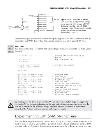
SMA wire Figure 25- 4 Two ways to activate
3 13
SMA wire 4 13 SMA wire via a microcontroller: using a
power transistor (in this case, a TIP120
5 12
1 kΩ
Control resistor TIP120 6 11 5v Darlington) and the trusty ULN2003
0 or 5v power integrated circuit. Shown here is an SMA
transistor 7 10
8 ULN2003 9 wire connected to one of the seven
drivers of the ULN2003.
vary the duty cycle (on- versus- off) of the short pulse applied to the wire. Experiment with the
time delays and PWM duty cycles. The example program uses a 3/4- second ON time.
101010 sma.pde
010101 You can also find this code at the RBB Online Support site. See Appendix A, “RBB Online
101010
Support.”
010101
int smaPin = 9; // Connect SMA driver circuit to
// pin D9
int ledPin = 13; // Use integrated LED
void setup()
{
pinMode(smaPin, OUTPUT); // Set pins as outputs
pinMode(ledPin, OUTPUT);
}
void loop()
{
digitalWrite(smaPin, HIGH); // Activate wire
digitalWrite(ledPin, HIGH); // Turn LED on
delay(250); // Keep on 1/4 second
digitalWrite(smaPin, LOW); // Deactivate wire
digitalWrite(ledPin, LOW); // Turn LED off
delay(5000); // Relax/cool for 5 seconds
analogWrite(smaPin, 128); // Activatde wire at 1/2 duty
digitalWrite(ledPin, HIGH); // Turn LED on
delay(750); // Keep on doer 1/2 second
digitalWrite(smaPin, LOW); // Deactivate wire
digitalWrite(ledPin, LOW); // Turn LED off
delay(5000); // Relax/cool for 5 seconds
}
Be sure to power the driver circuit for the SMA wire from its own battery or power supply. Do
not use the 5V pin on the Arduino to drive the wire, as the instantaneous current draw from the
wire could overwhelm the Arduino’s voltage regulator. As usual, be certain to connect the
grounds of the Arduino and your separate battery/power supply.
Experimenting with SMA Mechanisms
With the SMA properly terminated and actuated, it’s up to you and your own imagination to
think of ways to use it in your robots. Figure 25- 5 shows a typical application using an SMA
wire in a pulley configuration. Apply current to the wire and the pulley turns, giving you rota-
25-chapter-25.indd 291 4/21/11 11:51 AM