
Page 397 - Robot Builder's Bonanza
P. 397
366 BUILDING ROBOT ELECTRONICS— THE BASICS
minimal, so you may want to purchase a separate set that’s better. The coiled kind is handy;
the test leads stretch out to several feet, yet recoil to a manageable length when not in use.
Standard point- tip leads are fine for most routine testing, but some measurements may
require that you use a clip lead. These attach to the end of the regular test leads and have a
spring- loaded clip on the end. You can clip the lead in place so your hands are free to do other
things. The clips are insulated with plastic to prevent short circuits.
Using the Meter: The Basics
To use your multimeter, first set it next to whatever circuit you’re testing. Make sure it’s close
enough so the test leads reach the circuit without any risk of pulling either the meter or the
circuit into your lap. Then start with this:
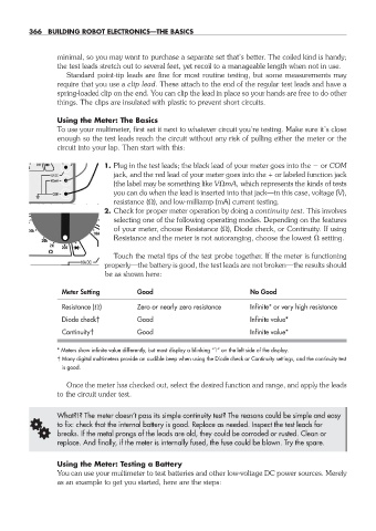
1. Plug in the test leads; the black lead of your meter goes into the or COM
jack, and the red lead of your meter goes into the + or labeled function jack
(the label may be something like V mA, which represents the kinds of tests
you can do when the lead is inserted into that jack— in this case, voltage (V),
resistance ( ), and low- milliamp (mA) current testing.
2. Check for proper meter operation by doing a continuity test. This involves
selecting one of the following operating modes. Depending on the features
of your meter, choose Resistance ( ), Diode check, or Continuity. If using
Resistance and the meter is not autoranging, choose the lowest setting.
Touch the metal tips of the test probe together. If the meter is functioning
properly— the battery is good, the test leads are not broken— the results should
be as shown here:
Meter Setting Good No Good
Resistance ( ) Zero or nearly zero resistance Infinite* or very high resistance
Diode check† Good Infinite value*
Continuity† Good Infinite value*
* Meters show infinite value differently, but most display a blinking “1” on the left side of the display.
† Many digital multimeters provide an audible beep when using the Diode check or Continuity settings, and the continuity test
is good.
Once the meter has checked out, select the desired function and range, and apply the leads
to the circuit under test.
What?!? The meter doesn’t pass its simple continuity test? The reasons could be simple and easy
G to fix: check that the internal battery is good. Replace as needed. Inspect the test leads for
breaks. If the metal prongs of the leads are old, they could be corroded or rusted. Clean or
replace. And finally, if the meter is internally fused, the fuse could be blown. Try the spare.
Using the Meter: Testing a Battery
You can use your multimeter to test batteries and other low- voltage DC power sources. Merely
as an example to get you started, here are the steps:
30-chapter-30.indd 366 4/21/11 11:55 AM