
Page 404 - Robot Builder's Bonanza
P. 404
HOW TO SOLDER 373
SETTING THE CORRECT SOLDERING TEMPERATURE
A soldering tool with a temperature control is often referred to as a soldering station. If that’s
what you’ve got, and you’re using traditional lead- bearing solder, dial the station to between
665°and 680°F (352° to 360°C). This provides maximum heat while posing the minimum
danger of damage to the electronic components.
If your soldering pencil/station has just the control and lacks a heat readout, initially set it
to low. Wait a few minutes for it to heat up, then try one or two test connections. Adjust the
heat control so that solder flows onto the connection in under 5 seconds.
To do its job, your soldering tool needs to be significantly hotter than the melting point of solder.
G Most lead- bearing solders have a melting point of about 362°F (183°C). For lead- free solder,
the range is much wider, but in general their melting point is 40° to 70°F higher. Increase the
temperature of the soldering tool accordingly.
STEPS FOR SUCCESSFUL SOLDERING
The idea behind successful soldering is to use the soldering tool to heat up the work— whether
it is a component lead, a wire, or whatever. You then apply the solder to the work. Don’t
apply solder directly to the soldering pencil. If you take that shortcut, you might end up with
a “cold” solder joint. A cold joint doesn’t adhere well to the metal surfaces of the part or
board, so electrical connection is impaired.
Here are the steps to solder a component onto a circuit board:
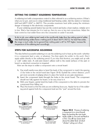
1. Use small needle- nose pliers to bend the leads of the component to match the spacing
of the holes in the circuit board (see Figure 30- 8). Eyeball the correct distance; you’ll
get more accurate at judging where to place the bends as you gain experience.
2. Insert the component leads through the holes in the circuit board. The component
should rest fully against the board, or be very close to it.
3. With your fingers, gently bend the leads of the component to the sides to prevent the
component from falling out.
4. Place the board so that the side you are soldering faces you. Apply the tip of the solder-
ing pencil against both the component lead and the “pad” around the hole.
Bend component leads Slightly bend out leads to
to match hole spacing keep component in place
in circuit board while you solder
Figure 30- 8 Process of soldering
a component to a circuit board.
Begin by bending the wire leads.
Apply solder to one pad and lead at
a time. Clip off any excess lead
above the solder level. (A short
Solder component leads Clip off excess lead
to circuit board above solder level “whisker” jutting out is fine.)
30-chapter-30.indd 373 4/21/11 11:55 AM