
Page 467 - Robot Builder's Bonanza
P. 467
436 AN OVERVIEW OF ROBOT “BRAINS”
On most microcontrollers, there is a critical shortage of I/O pins, so using parallel
G communications for everything uses up valuable data lines. To circumvent this, you can use
simple and inexpensive electronics to convert serial data to parallel. You can also do the
inverse. See Chapter 40, “Interfacing Hardware with Your Microcontroller or Computer,” for
more details on using serial- to- parallel and parallel- to- serial conversion.
ANALOG AND DIGITAL CONVERSION
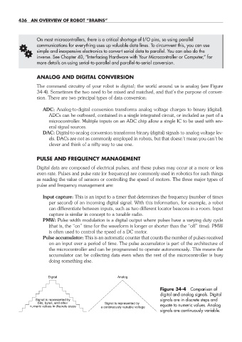
The command circuitry of your robot is digital; the world around us is analog (see Figure
34- 4). Sometimes the two need to be mixed and matched, and that’s the purpose of conver-
sion. There are two principal types of data conversion:
ADC: Analog- to- digital conversion transforms analog voltage charges to binary (digital).
ADCs can be outboard, contained in a single integrated circuit, or included as part of a
microcontroller. Multiple inputs on an ADC chip allow a single IC to be used with sev-
eral signal sources.
DAC: Digital- to- analog conversion transforms binary (digital) signals to analog voltage lev-
els. DACs are not as commonly employed in robots, but that doesn’t mean you can’t be
clever and think of a nifty way to use one.
PULSE AND FREQUENCY MANAGEMENT
Digital data are composed of electrical pulses, and these pulses may occur at a more or less
even rate. Pulses and pulse rate (or frequency) are commonly used in robotics for such things
as reading the value of sensors or controlling the speed of motors. The three major types of
pulse and frequency management are:
Input capture: This is an input to a timer that determines the frequency (number of times
per second) of an incoming digital signal. With this information, for example, a robot
can differentiate between inputs, such as two different locator beacons in a room. Input
capture is similar in concept to a tunable radio.
PMW: Pulse width modulation is a digital output where pulses have a varying duty cycle
(that is, the “on” time for the waveform is longer or shorter than the “off” time). PMW
is often used to control the speed of a DC motor.
Pulse accumulator: This is an automatic counter that counts the number of pulses received
on an input over a period of time. The pulse accumulator is part of the architecture of
the microcontroller and can be programmed to operate autonomously. This means the
accumulator can be collecting data even when the rest of the microcontroller is busy
doing something else.
Digital Analog
Figure 34- 4 Comparison of
digital and analog signals. Digital
Signal is represented by signals are in discrete steps and
bits, bytes, and other Signal is represented by
numeric values in discrete steps a continuously variable voltage equate to numeric values. Analog
signals are continuously variable.
34-chapter-34.indd 436 4/21/11 11:57 AM