
Page 259 -
P. 259
242 Computed-Torque Control
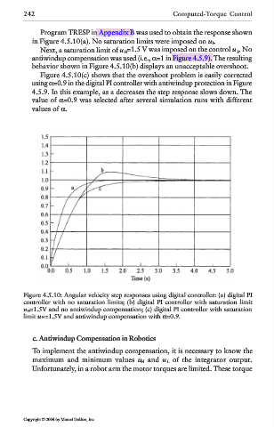
Program TRESP in Appendix B was used to obtain the response shown
in Figure 4.5.10(a). No saturation limits were imposed on u k .
Next, a saturation limit of u H =1.5 V was imposed on the control u k . No
antiwindup compensation was used (i.e., α=1 in Figure 4.5.9). The resulting
behavior shown in Figure 4.5.10(b) displays an unacceptable overshoot.
Figure 4.5.10(c) shows that the overshoot problem is easily corrected
using α=0.9 in the digital PI controller with antiwindup protection in Figure
4.5.9. In this example, as a decreases the step response slows down. The
value of α=0.9 was selected after several simulation runs with different
values of α.
Figure 4.5.10: Angular velocity step responses using digital controller: (a) digital PI
controller with no saturation limits; (b) digital PI controller with saturation limit
u H =1.5V and no antiwindup compensation; (c) digital PI controller with saturation
limit u H=1.5V and antiwindup compensation with α=0.9.
c. Antiwindup Compensation in Robotics
To implement the antiwindup compensation, it is necessary to know the
maximum and minimum values u H and u L of the integrator output.
Unfortunately, in a robot arm the motor torques are limited. These torque
Copyright © 2004 by Marcel Dekker, Inc.