
Page 254 -
P. 254
4.5 Digital Robot Control 237
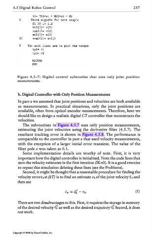
Figure 4.5–7: Digital control subroutine that uses only joint position
measurements.
b. Digital Controller with Only Position Measurements
In part a we assumed that joint positions and velocities are both available
as measurements. In practical situations, only the joint positions are
available, often from optical encoder measurements. Therefore, here we
should like to design a realistic digital CT controller that reconstructs the
velocities.
The subroutines in Figure 4.5.7 uses only position measurements,
estimating the joint velocities using the derivative filter (4.5.7). The
resultant tracking error is shown in Figure 4.5.8. The performance is
comparable to the controller in part a that used velocity measurements,
with the exception of a larger initial error transient. The value of the
filter pole v was taken as 0.1.
Some implementation details are worthy of note. First, it is very
important how the digital controller is initialized. Note the code lines that
zero the velocity estimates in the first iteration (IK=0). It is a good exercise
to repeat this simulation deleting these lines (see the Problems).
Second, it might be thought that a reasonable procedure for finding the
velocity error k= (kT) is to find an estimate v k of the joint velocity k and
then use
(1)
There are two disadvantages to this. First, it requires the storage in memory
of the desired velocity as well as the desired trajectory Second, it does
not work.
Copyright © 2004 by Marcel Dekker, Inc.