
Page 252 -
P. 252
4.5 Digital Robot Control 235
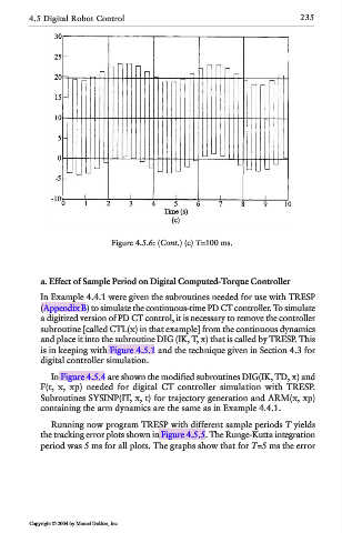
Figure 4.5.6: (Cont.) (c) T=100 ms.
a. Effect of Sample Period on Digital Computed-Torque Controller
In Example 4.4.1 were given the subroutines needed for use with TRESP
(Appendix B) to simulate the continuous-time PD CT controller. To simulate
a digitized version of PD CT control, it is necessary to remove the controller
subroutine [called CTL(x) in that example] from the continuous dynamics
and place it into the subroutine DIG (IK, T, x) that is called by TRESP. This
is in keeping with Figure 4.5.1 and the technique given in Section 4.3 for
digital controller simulation.
In Figure 4.5.4 are shown the modified subroutines DIG(IK, TD, x) and
F(t, x, xp) needed for digital CT controller simulation with TRESP.
Subroutines SYSINP(IT, x, t) for trajectory generation and ARM(x, xp)
containing the arm dynamics are the same as in Example 4.4.1.
Running now program TRESP with different sample periods T yields
the tracking error plots shown in Figure 4.5.5. The Runge-Kutta integration
period was 5 ms for all plots. The graphs show that for T=5 ms the error
Copyright © 2004 by Marcel Dekker, Inc.