
Page 133 - Robot Builders Source Book - Gordon McComb
P. 133
122 Kinematics and Control of Automatic Machines
FIGURE 4.9 Crankshaft mechanism.
in the same manner. Thus, the position function is expressed separately for each coor-
dinate. Obviously, this analytical approach can be useful for analyzing other specific
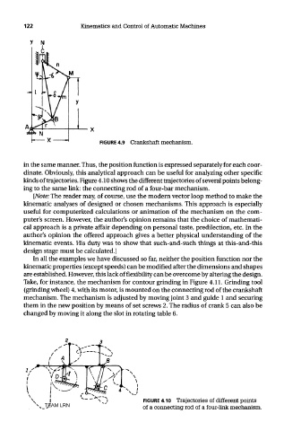
kinds of trajectories. Figure 4.10 shows the different trajectories of several points belong-
ing to the same link: the connecting rod of a four-bar mechanism.
[Note: The reader may, of course, use the modern vector loop method to make the
kinematic analyses of designed or chosen mechanisms. This approach is especially
useful for computerized calculations or animation of the mechanism on the com-
puter's screen. However, the author's opinion remains that the choice of mathemati-
cal approach is a private affair depending on personal taste, predilection, etc. In the
author's opinion the offered approach gives a better physical understanding of the
kinematic events. His duty was to show that such-and-such things at this-and-this
design stage must be calculated.]
In all the examples we have discussed so far, neither the position function nor the
kinematic properties (except speeds) can be modified after the dimensions and shapes
are established. However, this lack of flexibility can be overcome by altering the design.
Take, for instance, the mechanism for contour grinding in Figure 4.11. Grinding tool
(grinding wheel) 4, with its motor, is mounted on the connecting rod of the crankshaft
mechanism. The mechanism is adjusted by moving joint 3 and guide 1 and securing
them in the new position by means of set screws 2. The radius of crank 5 can also be
changed by moving it along the slot in rotating table 6.
FIGURE 4.10 Trajectories of different points
TEAM LRN of a connecting rod of a four-link mechanism.