
Page 137 - Robot Builders Source Book - Gordon McComb
P. 137
126
Kinematics and Control of Automatic Machines
FIGURE 4.15 Generalized concept of a
main camshaft.
FIGURE 4.16 Complexity of motion transforma-
tions carried out by purely mechanical means;
see text for explanation.
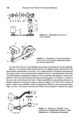
To make the structure more flexible, some kinds of transmission can be adopted.
Figure 4.17a) presents a ball transmission for very lightly loaded mechanisms. The
action of this transmission is obvious—it is a rough model of a hydraulic transmission.
For larger loads it is recommended that cylindrical inserts 1 be used between the balls.
A purely hydraulic transmission (Figure 4.17b)) can also be used. BeUows 1 on the cam-
follower's side transmits pressure through connecting pipe 3 to bellows 2, located on
the tool side, and actuates the latter. A third possibility for transmitting motion in a
flexible manner by mechanical means is shown in Figure 4.18. This device consists of
guide 1 made of some flexible metal in which plastic ribbon 2, which possesses open-
ings, is borne. The friction between the ribbon and the guide is reduced by proper
FIGURE 4.17 Models of a "flexible" trans-
mission of the camfollower's motion: a) Ball
transmission; b) Hydraulic transmission.
TEAM LRN