
Page 140 - Robot Builders Source Book - Gordon McComb
P. 140
4.2 Camshafts 129
For the central mechanism, where e = 0, we obtain a simpler expression for (4.23), i.e.:
or
The larger the pressure angle a, the lower the efficiency of the mechanism. When
this angle reaches a critical value, the mechanism can jam. The critical value of the
pressure angle depends on the friction conditions of the follower in its guides, on the
geometry of the guides, on the design of the follower (a flat follower always yields a = 0
but causes other restrictions), and on the geometry of the mechanism. To reduce the
pressure angle, we must analyze Expressions (4.23) and (4.24). It follows from them
that the pressure angle decreases as:
1. The value of a or r 0 increases;
2. The IT(0) function that describes the slope of the profile decreases.
Taking advantage of the first conclusion is impractical since it involves enlarging
the dimensions of the mechanism. Thus, we usually recommend use of the second
conclusion, that is, to "spread" the profile over a wider profile angle. However, to stay
within the limits determined by the timing diagram, we must increase the rotating
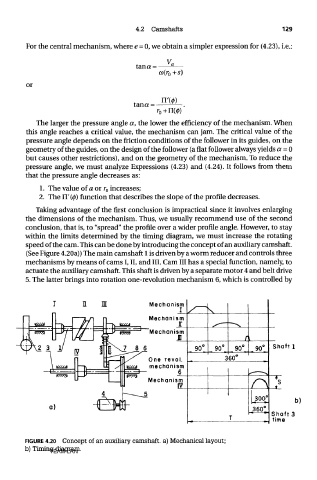
speed of the cam. This can be done by introducing the concept of an auxiliary camshaft.
(See Figure 4.20a)) The main camshaft 1 is driven by a worm reducer and controls three
mechanisms by means of cams I, II, and III. Cam III has a special function, namely, to
actuate the auxiliary camshaft. This shaft is driven by a separate motor 4 and belt drive
5. The latter brings into rotation one-revolution mechanism 6, which is controlled by
FIGURE 4.20 Concept of an auxiliary camshaft, a) Mechanical layout;
b) Timing diagram.
TEAM LRN