
Page 143 - Robot Builders Source Book - Gordon McComb
P. 143
132 Kinematics and Control of Automatic Machines
FIGURE 4.24 Arrangement for rapid cam
profile exchange.
FIGURE 4.25 Arrangement for rapid timing change.
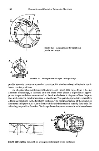
profile. Here the cam is composed of parts A and B, which can be fixed by bolts in dif-
ferent relative positions.
Use of a spatial cam introduces flexibility, as in Figure 4.26. Here, drum 1, having
a system of openings, is fastened onto the shaft, while pieces 2 of profiles of appro-
priate shapes and sizes are mounted on the drum by bolts. A diagram of how the pro-
files are located on the drum surface is also shown. The spatial approach to cams offers
additional solutions to the flexibility problem. The common feature of the examples
illustrated in Figures 4.27-4.29 is the use of the third dimension, namely the z-axis, for
adjusting the position function. To change the s value, one can use the solutions shown
FIGURE 4.26 Spatial cam with an arrangement for rapid profile exchange.
TEAM LRN