
Page 146 - Robot Builders Source Book - Gordon McComb
P. 146
4.3 Master Controller, Amplifiers 135
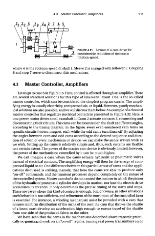
FIGURE 4.31 Layout of a cam drive for
considerable reduction of the cam's
rotation speed.
where n is the rotation speed of shaft 1. Sleeve 2 is engaged with follower 3. Coupling
6 and stop 7 serve to disconnect this mechanism.
4.3 Master Controller, Amplifiers
Let us go to case 6 in Figure 1.5. Here, control is effected through an amplifier. There
are several standard solutions for this type of kinematic layout. One is the so-called
master controller, which can be considered the simplest program carrier. The ampli-
fying energy is usually electricity, compressed air, or liquid. However, purely mechan-
ical solutions are also possible, and we will discuss them below. An example of a classical
master controller that regulates electrical contacts is presented in Figure 4.32. Here, a
low-power motor drives small camshaft 1. Cams 2 actuate contacts 3, connecting and
disconnecting their circuits. The cams can be mounted on the shaft at different angles,
according to the timing diagram. In the figure, every even-numbered cam turns on
specific circuits (motor, magnet, etc.), while the odd cams turn them off. By adjusting
the angles between even and odd cams according to the desired sequence and dura-
tion of action of every mechanism or device, we can make the entire system work as
we wish. Setting up the cams is relatively simple and, thus, such systems are flexible
to a certain extent. The power of the master cam device is obviously limited; however,
the power of the mechanisms controlled by it can be much higher.
We can imagine a case where the cams actuate hydraulic or pneumatic valves
instead of electrical contacts. The amplifying energy will then be the energy of com-
pressed liquid or air. One difference between this particular use of cams and the appli-
cations discussed is striking, namely, that here the cams are able to produce only
"on-off" commands, and the transient processes depend completely on the nature of
the controlled system. Master camshafts do not control the manner in which the piston
of the hydraulic or pneumatic cylinder develops its motion, nor how the electric drive
accelerates its rotation. It only determines the precise timing of the starts and stops.
There are cases where this kind of control is enough, but, of course, in other situations
such behavior is not sufficient, and refinement of the movement of the controlled item
is essential. For instance, a winding mechanism must be provided with a cam that
ensures uniform distribution of the turns of the reel; the cam that throws the shuttle
of a loom must develop an acceleration high enough to ensure travel of the shuttle
from one side of the produced fabric to the other.
We have seen that the cams in the mechanisms described above transmit practi-
cally no power and work on an "on-off" regime, turning real power transmitters on or
TEAM LRN