
Page 141 - Robot Builders Source Book - Gordon McComb
P. 141
130 Kinematics and Control of Automatic Machines
cam III. This cam actuates follower 8 by pressing against spring 7. The one-revolution
mechanism is then switched on, carries out one revolution, and stops. Obviously, the
speed of shaft 3 can be considerably higher than the rotational speed of camshaft 1.
Thus, cam iy which is mounted on shaft 3, completes its revolution much faster than
those on shaft 1.
The timing diagram shown in Figure 4.20b) is helpful here. According to this diagram,
auxiliary shaft 3 rotates four times faster than main camshaft 1; that is, during one-
quarter of a revolution of the main shaft, the auxiliary shaft completes a full revolu-
tion, then rests until shaft 1 finishes its revolution. This makes it possible to design the
profile of cam IV with a more gradual slope, thus reducing the pressure angle. In our
example, the profile of cam IV is extended over an angle of 300°, providing the needed
displacement s for the follower. Obviously, without the auxiliary shaft the same profile
must extend over an angle less than 90°, and the pressure angle would be much larger.
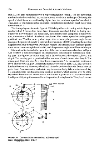
It is worthwhile to study the operation of the one-revolution mechanism. In Figure
4.21 we show a possible design of this mechanism, consisting of: permanently rotat-
ing part 1 (in Figure 4.20 motor 4 and belt 5 drive this part); driven part 2, key 3, and
stop 4. The rotating part is provided with a number of semicircular slots (say 6). The
driven part 2 has one slot. As is clear from cross section A-A, in a certain position of
key 3 (frontal view a)), part 1 can rotate freely around driven part 2 (i.e., key 3 does not
hinder this rotation). However, when key 3 takes the position shown in frontal view b),
parts 1 and 2 are connected and rotate together as one body. When not actuated, key
3 is usually kept in the disconnecting position by stop 4, which presses lever 3a of the
key. When the command to actuate the mechanism is given (cam III actuates follower
8 in Figure 4.20), stop 4 is removed from its position, freeing lever 3a. Thus, key 3 rotates
FIGURE 4.21 One-revolution mechanism: a) Disengaged
state; b) Engaged state; c) Key.
TEAM LRN