
Page 188 - Robot Builders Source Book - Gordon McComb
P. 188
176 Feedback Sensors
in Figure 5.la). When a constant voltage V 0 is introduced, the off-balance voltage AV
can be expressed as follows:
There are several methods to use these bridges. For instance, keeping the resis-
tances R-L, R 2, and R± constant so that R l = R 2 = R^ = R and using the resistance R 3 as a
sensor, i.e., a variable resistor responding to changes in the measured value, we can
rewrite Expression (5.1) as
Substituting here R 3 = R + Aft, where AR is a small change of the resistance, so as
AR«R we obtain, from (5.2),
In the simplest case, the displacement (or the measurement of some dimension)
is transformed directly into displacement of the slide arm of the resistor. Thus, as
follows from Relation (5.3), the change in the output voltage AV across the bridge's
diagonally opposite pair of terminals a-a is directly proportional to the displacement
(for small displacements). However, it is possible to increase the sensitivity of the bridge
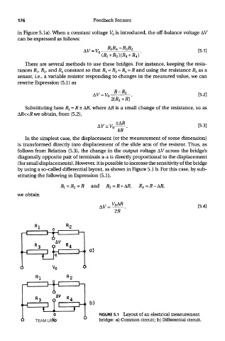
by using a so-called differential layout, as shown in Figure 5.1 b. For this case, by sub-
stituting the following in Expression (5.1),
we obtain
FIGURE 5.1 Layout of an electrical measurement
TEAM LRN bridge: a) Common circuit; b) Differential circuit.