
Page 183 - Robot Builders Source Book - Gordon McComb
P. 183
4.7 Electrically Controlled Vibration Dampers 171
FIGURE 4.68 Photograph of one of the DDs used
in our experiments.
FIGURE 4.69 Layout of an active damper. Force P changes
depending upon the free vibrations of the mass m.
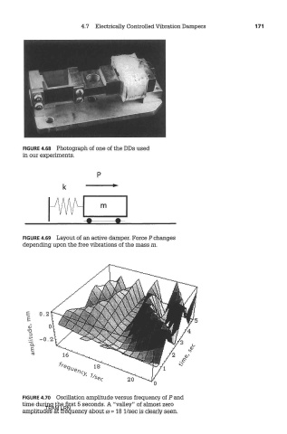
FIGURE 4.70 Oscillation amplitude versus frequency of P and
time during the first 5 seconds. A "valley" of almost zero
TEAM LRN
amplitudes at freo^iency about co = 18 I/sec is clearly seen.