
Page 26 - Robot Builders Source Book - Gordon McComb
P. 26
1.3 Manipulators 15
principle, any point inside the sphere can be reached by a gripper fixed to the end of
an arm. In reality, there are certain restrictions imposed by the real dimensions of the
links and the restraints of the joints which result in a dead zone in the middle of the
sphere. Sometimes the angle of rotation </> is also restricted (possibly because, for
instance, of the twisting of pipes or cables providing energy and a means of control to
the links).
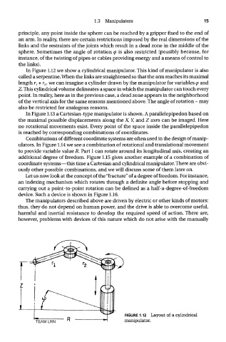
In Figure 1.12 we show a cylindrical manipulator. This kind of manipulator is also
called a serpentine. When the links are straightened so that the arm reaches its maximal
length r l + r 2, we can imagine a cylinder drawn by the manipulator for variables <p and
Z. This cylindrical volume delineates a space in which the manipulator can touch every
point. In reality, here as in the previous case, a dead zone appears in the neighborhood
of the vertical axis for the same reasons mentioned above. The angle of rotation ~ may
also be restricted for analogous reasons.
In Figure 1.13 a Cartesian-type manipulator is shown. A parallelepipedon based on
the maximal possible displacements along the X, Y, and Z axes can be imaged. Here
no rotational movements exist. Every point of the space inside the parallelepipedon
is reached by corresponding combinations of coordinates.
Combinations of different coordinate systems are often used in the design of manip-
ulators. In Figure 1.14 we see a combination of rotational and translational movement
to provide variable value R. Part 1 can rotate around its longitudinal axis, creating an
additional degree of freedom. Figure 1.15 gives another example of a combination of
coordinate systems—this time a Cartesian and cylindrical manipulator. There are obvi-
ously other possible combinations, and we will discuss some of them later on.
Let us now look at the concept of the "fracture" of a degree of freedom. For instance,
an indexing mechanism which rotates through a definite angle before stopping and
carrying out a point-to-point rotation can be denned as a half-a-degree-of-freedom
device. Such a device is shown in Figure 1.16.
The manipulators described above are driven by electric or other kinds of motors:
thus, they do not depend on human power, and the drive is able to overcome useful,
harmful and inertial resistance to develop the required speed of action. There are,
however, problems with devices of this nature which do not arise with the manually
FIGURE 1.12 Layout of a cylindrical
TEAM LRN manipulator.