
Page 25 - Robot Builders Source Book - Gordon McComb
P. 25
14 Introduction: Brief Historical Review and Main Definitions
in principle and in reality the teleoperator is able to perform many other manipula-
tions. Obviously the number of degrees of freedom attributable to a manipulator is
considerably less than the 27 degrees of freedom of the human arm. The operator of
such a device thus has to be specially skilled at working with it. At present, engineers
are nowhere near creating a manipulator with 27 degrees of freedom, which would be
able to replace, at least in kinematic terms, the human arm. An additional problem is
that a human arm, unlike a manipulator, is sensitive to the pressure developed, and
the temperature and the surface properties of the object it is gripping. To compensate
for the limited possibilities of the teleoperators, the workplace and the objects to be
manipulated have to be simplified and organized in a special way.
The distance between the control and serving arms can range from one meter to
tens of meters, and the maximum weight the manipulator can handle is 7-8 kg; i.e.,
the maximum weight the average person is able to manipulate for a defined period of
time. The friction forces and torques can reach 1-4 kg and 10-20 kg cm, respectively,
i.e., values which reduce the sensitivity of the device. Mechanical transmissions are
the simplest way of arranging the connections between the control and serving arms.
When the distance between the arms is large, the deformations become significant;
for example, for a distance of 1.5-2 m, a force of 8 kg causes a linear deformation of
50-60 mm and angular deflections of 3-8°.
An additional problem occurs as a result of the mass of the mechanical "arms." To
compensate for these weights, balance masses are used (in Figure 1.10 they are fas-
tened to the opposite branches of the cables where the bodies 4 and 5 are fastened).
This, in turn, increases both the forces of inertia developed when the system is in action
and the effort the operator has to apply to reach the required operating speed. Thus,
an ideal device which would be able to mimic, at any distance, the exact movement
of the operator's arm is still a dream.
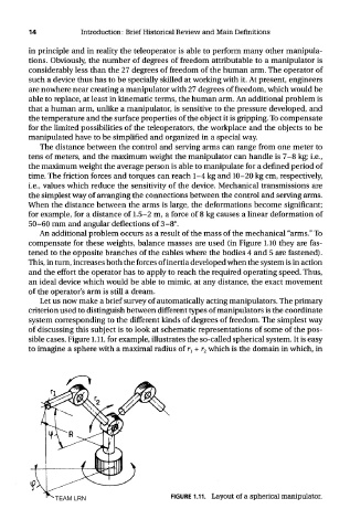
Let us now make a brief survey of automatically acting manipulators. The primary
criterion used to distinguish between different types of manipulators is the coordinate
system corresponding to the different kinds of degrees of freedom. The simplest way
of discussing this subject is to look at schematic representations of some of the pos-
sible cases. Figure 1.11, for example, illustrates the so-called spherical system. It is easy
to imagine a sphere with a maximal radius of r : + r 2 which is the domain in which, in
TEAM LRN FIGURE 1.11. Layout of a spherical manipulator.