
Page 35 - Robot Builders Source Book - Gordon McComb
P. 35
24 Introduction: Brief Historical Review and Main Definitions
The comparison of Expressions (1.6) and (1.7) proves that, for equal concepts
(T c ~ T], the continuous process is about (1 + 77) lr\ times more effective. This fact makes
the continuous approach very attractive, and a great deal of effort has been spent in
introducing this approach for the manufacturing and production of piece-type objects.
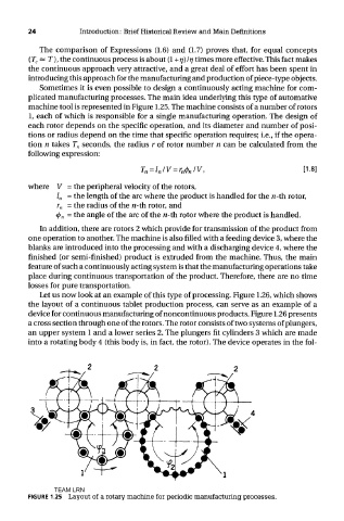
Sometimes it is even possible to design a continuously acting machine for com-
plicated manufacturing processes. The main idea underlying this type of automative
machine tool is represented in Figure 1.25. The machine consists of a number of rotors
1, each of which is responsible for a single manufacturing operation. The design of
each rotor depends on the specific operation, and its diameter and number of posi-
tions or radius depend on the time that specific operation requires; i.e., if the opera-
tion n takes T n seconds, the radius r of rotor number n can be calculated from the
following expression:
where V = the peripheral velocity of the rotors,
/„ = the length of the arc where the product is handled for the n-th rotor,
r n = the radius of the «-th rotor, and
(f) n - the angle of the arc of the n-th rotor where the product is handled.
In addition, there are rotors 2 which provide for transmission of the product from
one operation to another. The machine is also filled with a feeding device 3, where the
blanks are introduced into the processing and with a discharging device 4, where the
finished (or semi-finished) product is extruded from the machine. Thus, the main
feature of such a continuously acting system is that the manufacturing operations take
place during continuous transportation of the product. Therefore, there are no time
losses for pure transportation.
Let us now look at an example of this type of processing. Figure 1.26, which shows
the layout of a continuous tablet production process, can serve as an example of a
device for continuous manufacturing of noncontinuous products. Figure 1.26 presents
a cross section through one of the rotors. The rotor consists of two systems of plungers,
an upper system 1 and a lower series 2. The plungers fit cylinders 3 which are made
into a rotating body 4 (this body is, in fact, the rotor). The device operates in the fol-
TEAM LRN
FIGURE 1.25 Layout of a rotary machine for periodic manufacturing processes.