
Page 36 - Robot Builders Source Book - Gordon McComb
P. 36
1.4 Structure of Automatic Industrial Systems 25
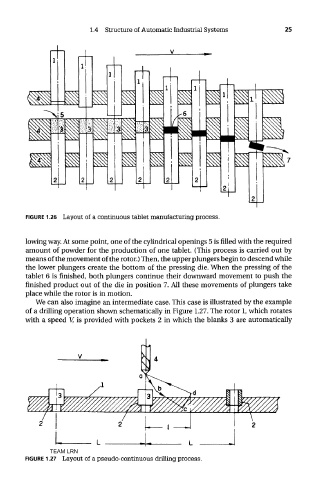
FIGURE 1.26 Layout of a continuous tablet manufacturing process.
lowing way. At some point, one of the cylindrical openings 5 is filled with the required
amount of powder for the production of one tablet. (This process is carried out by
means of the movement of the rotor.) Then, the upper plungers begin to descend while
the lower plungers create the bottom of the pressing die. When the pressing of the
tablet 6 is finished, both plungers continue their downward movement to push the
finished product out of the die in position 7. All these movements of plungers take
place while the rotor is in motion.
We can also imagine an intermediate case. This case is illustrated by the example
of a drilling operation shown schematically in Figure 1.27. The rotor 1, which rotates
with a speed V, is provided with pockets 2 in which the blanks 3 are automatically
TEAM LRN
FIGURE 1.27 Layout of a pseudo-continuous drilling process.