
Page 99 - Robot Builders Source Book - Gordon McComb
P. 99
88 Dynamic Analysis of Drives
Obviously, the calculations shown above answer the following questions:
• How long does it take for the drive to reach the desired angle or (using corre-
sponding transmission) displacement?
• How long does it take for the drive to reach the desired speed?
• What angle, displacement, or speed can be reached during a specific time interval?
• Which parameters of the motor must be taken into account to reach the desired
angle, displacement, or speed in a specific time?
3.4 Hydraulic Drive
Let us now learn how to estimate the displacement time of a mass driven by a hydro -
mechanism.
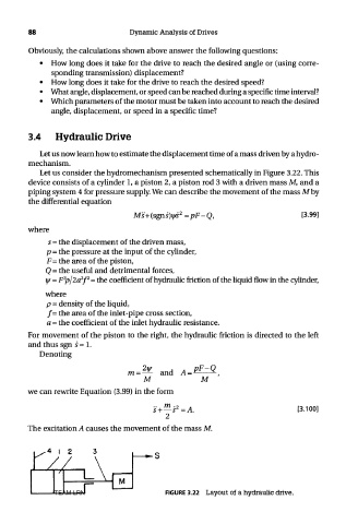
Let us consider the hydromechanism presented schematically in Figure 3.22. This
device consists of a cylinder 1, a piston 2, a piston rod 3 with a driven mass M, and a
piping system 4 for pressure supply. We can describe the movement of the mass Mby
the differential equation
where
5 = the displacement of the driven mass,
p = the pressure at the input of the cylinder,
F= the area of the piston,
Q = the useful and detrimental forces,
3
2 2
^ = F p/2a f = the coefficient of hydraulic friction of the liquid flow in the cylinder,
where
p = density of the liquid,
/= the area of the inlet-pipe cross section,
a = the coefficient of the inlet hydraulic resistance.
For movement of the piston to the right, the hydraulic friction is directed to the left
and thus sgn 5=1.
Denoting
we can rewrite Equation (3.99) in the form
The excitation A causes the movement of the mass M.
TEAM LRN FIGURE 3.22 Layout of a hydraulic drive.