
Page 211 - Robotics Designing the Mechanisms for Automated Machinery
P. 211
5.3 Force Sensors 199
This sensor consists of magnetic circuit 1, coil 2, and membrane 3 made of ferromag-
netic material and influenced by the measured pressure. The initial air gap between 3
and 2 is about 0.2-0.5 mm.
Figure 5.37 shows a capacitance sensor consisting of membrane 1, made as one
piece with the housing, and an immobile electrode 2 insulated from the housing by
bushing 3. The air gap between 1 and 2 must be as small as possible. The accuracy of
these devices is about 2%.
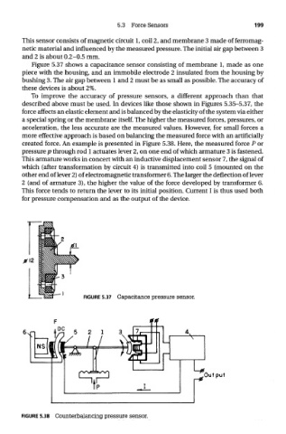
To improve the accuracy of pressure sensors, a different approach than that
described above must be used. In devices like those shown in Figures 5.35-5.37, the
force affects an elastic element and is balanced by the elasticity of the system via either
a special spring or the membrane itself. The higher the measured forces, pressures, or
acceleration, the less accurate are the measured values. However, for small forces a
more effective approach is based on balancing the measured force with an artificially
created force. An example is presented in Figure 5.38. Here, the measured force P or
pressure p through rod 1 actuates lever 2, on one end of which armature 3 is fastened.
This armature works in concert with an inductive displacement sensor 7, the signal of
which (after transformation by circuit 4) is transmitted into coil 5 (mounted on the
other end of lever 2) of electromagnetic transformer 6. The larger the deflection of lever
2 (and of armature 3), the higher the value of the force developed by transformer 6.
This force tends to return the lever to its initial position. Current I is thus used both
for pressure compensation and as the output of the device.
FIGURE 5.37 Capacitance pressure sensor.
FIGURE 5.38 Counterbalancing pressure sensor.