
Page 192 - Robots Androids and Animatrons : 12 Incredible Projects You Can Build
P. 192
Mount the metal in a vise and make the two 90 degree bends at the
marked lines to form the metal into a U bracket.
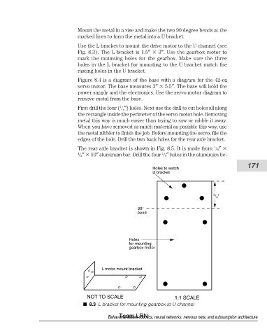
Use the L bracket to mount the drive motor to the U channel (see
Fig. 8.3). The L bracket is 1.5″ 3″. Use the gearbox motor to
mark the mounting holes for the gearbox. Make sure the three
holes in the L bracket for mounting to the U bracket match the
mating holes in the U bracket.
Figure 8.4 is a diagram of the base with a diagram for the 42-oz
servo motor. The base measures 3″ 5.5″. The base will hold the
power supply and the electronics. Use the servo motor diagram to
remove metal from the base.
1
First drill the four ( ″) holes. Next use the drill to cut holes all along
8
the rectangle inside the perimeter of the servo motor hole. Removing
metal this way is much easier than trying to saw or nibble it away.
When you have removed as much material as possible this way, use
the metal nibbler to finish the job. Before mounting the servo, file the
edges of the hole. Drill the two back holes for the rear axle bracket.
The rear axle bracket is shown in Fig. 8.5. It is made from 8″
1
1 1
2″ 10″ aluminum bar. Drill the four 8″ holes in the aluminum be-
171
Holes to watch
U bracket
3 / "
4
90°
bend
Holes
for mounting
gearbox motor
L motor mount bracket
NOT TO SCALE 1:1 SCALE
8.3 L bracket for mounting gearbox to U channel
Team LRN
Behavioral-based robotics, neural networks, nervous nets, and subsumption architecture