Page 197 - Robots Androids and Animatrons : 12 Incredible Projects You Can Build
P. 197

1
                                        1
                                                                                   1
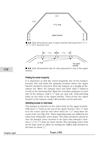
                                       4 / 2 "               3 / 2 "              4 / 2 "
                                                            1
                                                           14 / 2 " long

                                                         Upper bracket
                                    1"                                                 1"

                                                                                      1
                                  8.8 Side dimensional view of upper bracket fabricated from  / 8″
                                1       1
                                 / 2″   14 / 2″ aluminum bar


                                                       1
                                                                    1
                                                      1 / 8 "      1 / 8 "

                                           1 / 8 " hole
                                                                             Top upper
                                                                             bracket
                                  8.9 Side dimensional view for hole placement in top of the upper
           176
                                bracket

                                Finding the center of gravity
                                It is important to find the center-of-gravity line of the bumper,
                                because  this  will  mark  the  optimum  location  where  the  upper
                                bracket should be attached. Rest the bumper on a length of alu-
                                minum  bar.  Move  the  bumper  back  and  forth  until  it  balances
                                evenly on the aluminum bar. Mark the centerline positions on each
                                                         1
                                side of the bumper. Drill a    8″ hole on each side. Drill matching
                                holes on the ends of the upper bracket. Then secure the upper
                                bracket to the bumper using 5-40 machine screws and nuts.
                                Attaching bumper to robot base
                                The bumper is attached to the robot body by the upper bracket.
                                                                                    1
                                          1
                                Drill three    8″ holes in the top of the upper bracket. One    8″ hole
                                                                           1
                                is in the center and the two other holes are 1   8″ away from the
                                center hole (see Fig. 8.9). Three matching holes are drilled in the
                                robot base behind the servo motor. The holes should be placed so
                                that the bumper (once secured to the base) has adequate clear-
                                ance (   ″ to   ″) from the back wheels. The matching center hole
                                            1
                                      1
                                             4
                                       8
                                on the base must be offset by moving the drilled hole forward on
                                                 1
                                the base by about    ″.
                                                  4
                                                       Team LRN
            Chapter eight
   192   193   194   195   196   197   198   199   200   201   202