
Page 198 - Robots Androids and Animatrons : 12 Incredible Projects You Can Build
P. 198
brass nut
6-32
wire
machine
nut
screw 6-32 6-32 Soldered 6-32
nut
1" long 6-32 1" long
compression 1 / machine compression
spring 2 spring
6-32 screw
nut
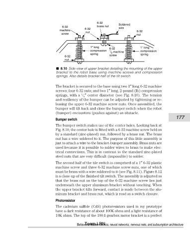
8.10 Side view of upper bracket detailing the mounting of the upper
bracket to the robot base using machine screws and compression
springs. Also details bracket half of the tilt switch
The bracket is secured to the base using two 1″ long 6-32 machine
screws; four 6-32 nuts; and two 1″ long, 2-pound (lb) compression
1
springs, with a ″ center diameter (see Fig. 8.10). The tension
8
and resiliency of the bumper can be adjusted by tightening or re-
leasing the upper 6-32 machine screw nuts. Once assembled, the
bumper will tilt back and close the bumper switch when the robot
(bumper) encounters (pushes against) an obstacle.
177
Bumper switch
The bumper switch makes use of the center holes. Looking back at
Fig. 8.10, the center hole is fitted with a 6-32 machine screw held on
by a standard (zinc-plated) nut, followed by a brass nut. The brass
nut has a wire soldered to it. The purpose of this little assembly is
just to attach a wire to the bracket-bumper assembly. Brass nuts are
used because it is possible to solder wires to brass to make elec-
trical connections. This is in contrast to the standard zinc-plated
steel nuts that are very difficult (impossible) to solder.
The second half of the tile switch is comprised of a 1″ 6-32 plastic
machine screw and three 6-32 machine screw nuts, one of which
must be brass with a wire soldered to it (see Fig. 8.11). Figure 8.12
is a close-up of the finished tilt switch. The assembly is adjusted so
that the brass nut on the top of the 6-32 machine screw lies just
underneath the upper aluminum bracket without touching. When
the upper bracket tilts forward, contact is made between the alu-
minum bracket and brass nut, which is read as a switch closure.
Photoresistor
The cadmium sulfide (CdS) photoresistors used in my prototype
have a dark resistance of about 100K ohms and a light resistance of
10K ohms. The top of the 100:1 gearbox motor bracket is a perfect
Team LRN
Behavioral-based robotics, neural networks, nervous nets, and subsumption architecture