
Page 200 - Robots Androids and Animatrons : 12 Incredible Projects You Can Build
P. 200
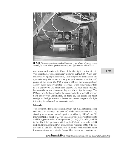
8.13 Close-up photograph detailing front drive wheel, showing coun-
                                       terweight, drive wheel, gearbox motor, and light sensor with shroud


                                       operation as described in Chap. 6 for the light tracker circuit.   179
                                       The operation of the sensor array is shown in Fig. 8.15. When both
                                       sensors are equally illuminated, their respective resistances are
                                       approximately  the  same.  As  long  as  each  sensor  is  within  ±10
                                       points of the other, the PIC program will see them as equal and
                                       doesn’t move the servo motor (steering). When either sensor falls
                                       in the shadow of the main light source, the resistance variance
                                       between the sensors increases beyond the ±10-point range. The
                                       PIC microcontroller activates the servo motor to bring both sensors
                                       back  under  even  illumination.  In  doing  so,  this  steers  the  robot
                                       straight to the light source. If the sensors detect too great of a light
                                       intensity, the robot will go into avoid mode.
                                       Schematic
                                       The schematic for the robot is shown in Fig. 8.16. Intelligence for
                                       the  robot  is  provided  by  two  PIC16F84  microcontrollers.  The
                                       steering servo motor control signal is provided by RB3 off the PIC
                                       microcontroller number 2. The 100:1 gearbox motor is attached to
                                       an H-bridge consisting of components Q1 to Q4, D1 to D4, and R1
                                       to R4. The H-bridge is controlled by the PIC microcontrollers RB1
                                       and RB2 input/output (I/O) lines. Sensor readings of the CdS cell
                                       are read off pin RB4. RB5 reads the tilt switch to check if the robot
                                       has encountered an obstacle. I assembled the entire circuit on two
                                                       Team LRN
                                                   Behavioral-based robotics, neural networks, nervous nets, and subsumption architecture