
Page 83 - Robots Androids and Animatrons : 12 Incredible Projects You Can Build
P. 83
R2
R1 R2
where Vcc 5 V. Vref Vcc
To make an adjustable voltage divider, use a potentiometer as
shown in Fig. 5.2B and C. I chose to use the Vref style of Fig. 5.2A
because it is simple.
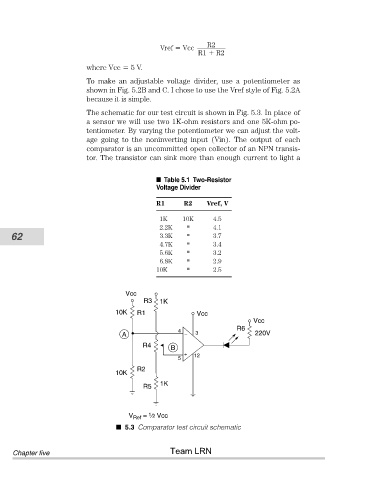
The schematic for our test circuit is shown in Fig. 5.3. In place of
a sensor we will use two 1K-ohm resistors and one 5K-ohm po-
tentiometer. By varying the potentiometer we can adjust the volt-
age going to the noninverting input (Vin). The output of each
comparator is an uncommitted open collector of an NPN transis-
tor. The transistor can sink more than enough current to light a
Table 5.1 Two-Resistor
Voltage Divider
R1 R2 Vref, V
1K 10K 4.5
2.2K '' 4.1
62 3.3K '' 3.7
4.7K '' 3.4
5.6K '' 3.2
6.8K '' 2.9
10K '' 2.5
Vcc
R3 1K
10K R1 Vcc
Vcc
R6
4 3
A – 220V
R4
B
+ 12
5
R2
10K
1K
R5
V Ref = ⁄2 Vcc
1
5.3 Comparator test circuit schematic
Team LRN
Chapter five