
Page 84 - Robots Androids and Animatrons : 12 Incredible Projects You Can Build
P. 84
light-emitting diode (LED), which we can use as an indicator. In ad-
dition, the output may be used as a simple single-pole, single-
throw (SPST) switch to ground. This feature will be useful when
we later need to trigger a 555 timer.
With the circuit wired, let’s see what happens. When the input
voltage (Vin) is less than the reference voltage (Vref), the output is
0 V (ground) and the LED is forward-biased and lit. If we adjust the
potentiometer so that the voltage is greater than Vref, the output
of the comparator goes high, turning off the LED. You can verify
the operation of the comparator by using a voltmeter to measure
the voltages at points A (Vref) and B (Vin).
Many people (myself included) feel this circuit is counterintu-
itive. I would like the LED to be lit when the sensor voltage is
higher than the reference voltage. This can be accomplished by
reversing the input leads and connecting the inverting input ( )
Vin and the noninverting input to Vref. The output function re-
verses also.
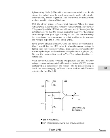
When one doesn’t need too many comparators, you may consider
using a complementary metal oxide semiconductor (CMOS) op-amp
configured as a comparator. The reason I like to use an op-amp is
that it can source (supply) sufficient current to drive an LED or cir- 63
cuit directly (see Fig. 5.4).
Vcc Vcc Vcc
1K
15K
2 7
–
6
5K
3
+ 4 *
15K
1K
CMOS Op-amp
Comparator
* Sub miniature LED
5.4 Comparator op-amp test circuit schematic
Team LRN Sensors