
Page 89 - Robots Androids and Animatrons : 12 Incredible Projects You Can Build
P. 89
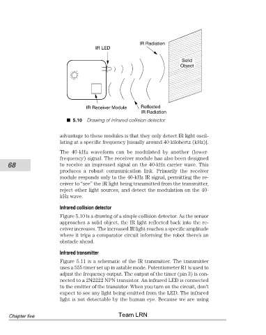
IR LED            IR Radiation
                                                                                 Solid
                                                                                Object


                                          IR Receiver Module    Reflected
                                                                IR Radiation
                                     5.10 Drawing of infrared collision detector


                                advantage to these modules is that they only detect IR light oscil-
                                lating at a specific frequency [usually around 40 kilohertz (kHz)].
                                The  40-kHz  waveform  can  be  modulated  by  another  (lower-
                                frequency) signal. The receiver module has also been designed
           68                   to receive an impressed signal on the 40-kHz carrier wave. This
                                produces  a  robust  communication  link.  Primarily  the  receiver
                                module responds only to the 40-kHz IR signal, permitting the re-
                                ceiver to “see” the IR light being transmitted from the transmitter,
                                reject other light sources, and detect the modulation on the 40-
                                kHz wave.

                                Infrared collision detector
                                Figure 5.10 is a drawing of a simple collision detector. As the sensor
                                approaches a solid object, the IR light reflected back into the re-
                                ceiver increases. The increased IR light reaches a specific amplitude
                                where it trips a comparator circuit informing the robot there’s an
                                obstacle ahead.

                                Infrared transmitter
                                Figure 5.11 is a schematic of the IR transmitter. The transmitter
                                uses a 555 timer set up in astable mode. Potentiometer R1 is used to
                                adjust the frequency output. The output of the timer (pin 3) is con-
                                nected to a 2N2222 NPN transistor. An infrared LED is connected
                                to the emitter of the transistor. When you turn on the circuit, don’t
                                expect to see any light being emitted from the LED. The infrared
                                light is not detectable by the human eye. Because we are using

                                                       Team LRN
            Chapter five