
Page 90 - Robots Androids and Animatrons : 12 Incredible Projects You Can Build
P. 90
1K R1 Vcc R3
220
8 4
7 210222
4.7K 555 3 1K
R2 6
2
1
.0047 D1
F
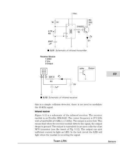
5.11 Schematic of infrared transmitter
Receiver Module
1 GND
2 Vcc
3 Output
NPN Output
69
12 3 220
R1
+
5V
–
.1 F
5.12 Schematic of infrared receiver
this in a simple collision detector, there is no need to modulate
the 40-kHz signal.
Infrared receiver
Figure 5.12 is a schematic of the infrared receiver. The receiver
module is an Everlite IRM-8420. The center frequency is 37.9 kHz
with a bandwidth of 3 kHz (±1.5 kHz). The output is active low. This
means that when the receiver module detects the signal, the output
drops to ground. The output is equivalent to an open collector of an
NPN transistor (see the insert of Fig. 5.12). The output can sink
sufficient current to light an LED. In the test circuit the LED will
light when the module is receiving the signal.
Team LRN Sensors