
Page 95 - Robots Androids and Animatrons : 12 Incredible Projects You Can Build
P. 95
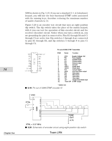
5089 is shown in Fig. 5.19. If you use a standard 3   4 (telephone)
                                keypad, you will lose the four functional DTMF codes associated
                                with the missing keys, therefore reducing the maximum number
                                of usable channels to 12.
                                Figure 5.20 is an encoder test circuit that uses an eight-position
                                dip switch. The dip switch takes the place of the matrix keypad;
                                with it you can test the operation of this encoder circuit and the
                                receiver (decoder) circuit. Notice when you turn a switch on, you
                                are grounding the pin it is connected to. Pins R1 through R4 and C1
                                through C4 are active low. Dip switches 1 through 4 are connected
                                to pins R1 through R4, and dip switches 5 through 8 to pins C1
                                through C4.


           74


                                  5.19 Pin out of 5089 DTMF encoder IC


                                     VDD
                                       1
                                       15     9
                                              5
                                XTAL
                                              4
                                       7
                                              3
                                       8
                                       6    5089  14
                                             13
                                             12
                                             11
                                             16                          TONE
                                                                          OUT
                                                                          4.7K
                                 XTAL = 3.57 MHz
                                  5.20 Schematic of encoder circuit using eight-position dip switch
                                                       Team LRN
            Chapter five