
Page 99 - Robots Androids and Animatrons : 12 Incredible Projects You Can Build
P. 99
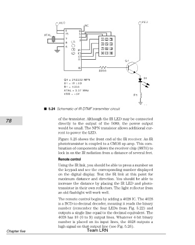
5.24 Schematic of IR DTMF transmitter circuit


           78                           of the transistor. Although the IR LED may be connected
                                        directly  to  the  output  of  the  5089,  the  power  output
                                        would be small. The NPN transistor allows additional cur-
                                        rent to power the LED.

                                        Figure 5.25 shows the front end of the IR receiver. An IR
                                        phototransistor is coupled to a CMOS op-amp. This com-
                                        bination of components allows the receiver chip (8870) to
                                        lock in on the IR radiation from a distance of several feet.
                                        Remote control
                                        Using the IR link, you should be able to press a number on
                                        the keypad and see the corresponding number displayed
                                        on  the  digital  display.  Test  the  IR  link  at  this  point  for
                                        maximum distance and direction. You should be able to
                                        increase the distance by placing the IR LED and photo-
                                        transistor in their own reflectors. The light reflector from
                                        an old flashlight will work well.
                                        The remote control begins by adding a 4028 IC. The 4028
                                        is a BCD-to-decimal decoder, meaning it reads the binary
                                        number (remember the four LEDs from Fig. 5.22) and
                                        outputs a single line equal to the decimal equivalent. The
                                        4028 has 10 (0 to 9) output lines. Whatever 4-bit binary
                                        number is placed on its input lines, the 4028 outputs a
                                        high signal on that output line (see Fig. 5.26).
            Chapter five                               Team LRN