
Page 104 - Robots Androids and Animatrons : 12 Incredible Projects You Can Build
P. 104
Top view, looking down
through sensor to leads
Vcc
10 mF + 1K 1K 1K 1K
7805 +5v Vcc
Vcc
1 2 3
3 1
9V + 2 2
1 3
3 2 1
–
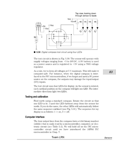
5.30 Digital compass test circuit using four LEDs
The test circuit is shown in Fig. 5.30. The sensor will operate with
supply voltages ranging from 5 to 18VDC. A 9V battery is used
as a power source and is regulated to 5V using a 7805 voltage
regulator.
As a rule, try to keep all voltages at 5 V maximum. This will make it 83
computer-safe. For instance, when the digital compass is inter-
faced to the PIC microcontrollers, if we forgot and used a 9V power
source on the compass, the outputs may damage the input/output
(I/O) inputs.
The test circuit uses four LEDs for display. As the sensor is rotated,
each cardinal position on the compass will light one LED. The inter-
mediate directions light two LEDs.
Testing and calibration
Find north using a standard compass. Rotate the circuit so that
one LED is lit. I used the LED furthest away from the sensor for
north. If you do the same, the other LEDs will automatically follow
the same sequence outlined (see Fig. 5.31). The sequence for my
display is as follows: 1 on, 0 off.
Computer interface
The four output lines from the compass form a 4-bit binary number
(nibble) that is easily read by a microcontroller, computer, or elec-
tronic circuit (see Table 5.4). We will hold off on the PIC micro-
controller circuit until we have introduced the 16F84 PIC
microcontroller in Chap. 7.
Team LRN Sensors