
Page 109 - Robots Androids and Animatrons : 12 Incredible Projects You Can Build
P. 109
R3
22K
R1 Vcc
1K
2
– Output Output
U1 7 VOM
+ 6
3 4 Volts
Ultra Sonic V
Transducer R4 .1 F
R2 1K 1Meg 16V
Tuning
Test Circuits
CMOS Comparator
Vcc
220 R4
4.7 R5
K
2 Signal
U1 = CMOS Op-amp – 7 6 out
88 Vcc = 5 Vac Input 4 220
3 +
220
220
R6
* Submini
LED
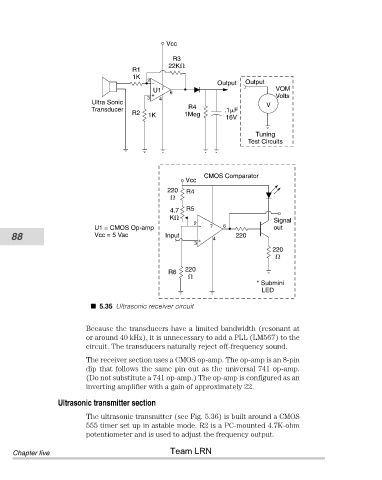
5.35 Ultrasonic receiver circuit
Because the transducers have a limited bandwidth (resonant at
or around 40 kHz), it is unnecessary to add a PLL (LM567) to the
circuit. The transducers naturally reject off-frequency sound.
The receiver section uses a CMOS op-amp. The op-amp is an 8-pin
dip that follows the same pin out as the universal 741 op-amp.
(Do not substitute a 741 op-amp.) The op-amp is configured as an
inverting amplifier with a gain of approximately 22.
Ultrasonic transmitter section
The ultrasonic transmitter (see Fig. 5.36) is built around a CMOS
555 timer set up in astable mode. R2 is a PC-mounted 4.7K-ohm
potentiometer and is used to adjust the frequency output.
Team LRN
Chapter five