
Page 110 - Robots Androids and Animatrons : 12 Incredible Projects You Can Build
P. 110
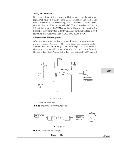
Tuning the transmitter
                                       Set up the ultrasonic transducers so that they are directly facing one
                                       another about 4″ to 5″ apart (see Fig. 5.37). Connect the VOM to the
                                       circuit as shown in the insert in Fig. 5.35. (Leave the comparator sec-
                                       tion off.) Set the VOM to read volts DC. You will need to read about
                                       2 V; set the range on the VOM accordingly. Turn on both circuits. Ad-
                                       just R2 of the transmitter so that you obtain the peak voltage output
                                       shown on the voltmeter. This should read about 2 VDC.
                                       Adjusting the CMOS comparator
                                       After tuning the transmitter, we need to set the receiver’s com-
                                       parator  circuit.  Disconnect  the  VOM  from  the  receiver  section
                                       and connect the CMOS comparator. Rearrange the transducers so
                                       that they are lying side by side about half an inch apart facing in
                                       the same direction. Place a flat-sided solid object about 3″ in front


                                                               Vcc

                                                                            R3
                                             1K   R1                        220
                                                          8  4
                                                                 210222
                                                         7     3                                            89
                                           4.7K                   1K
                                           R2                555
                                                         6                           Ultrasonic
                                                                                     Transducer
                                                         2   1
                                           .0047
                                             F


                                                      Vcc = 5Volts

                                             * Use CMOS 555 Timer
                                         5.36 Ultrasonic transmitter circuit


                                        Transmitter                                        Voltmeter
                                        Circuit                                Receiver
                                                                               Circuit


                                                              4–5"
                                         5.37 Ultrasonic test setup
                                                       Team LRN                                         Sensors