
Page 98 - Robots Androids and Animatrons : 12 Incredible Projects You Can Build
P. 98
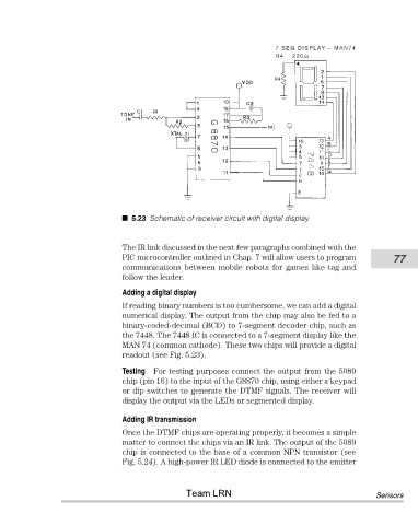
5.23 Schematic of receiver circuit with digital display


                                       The IR link discussed in the next few paragraphs combined with the
                                       PIC microcontroller outlined in Chap. 7 will allow users to program  77
                                       communications between mobile robots for games like tag and
                                       follow the leader.

                                       Adding a digital display
                                       If reading binary numbers is too cumbersome, we can add a digital
                                       numerical display. The output from the chip may also be fed to a
                                       binary-coded-decimal (BCD) to 7-segment decoder chip, such as
                                       the 7448. The 7448 IC is connected to a 7-segment display like the
                                       MAN 74 (common cathode). These two chips will provide a digital
                                       readout (see Fig. 5.23).

                                       Testing For testing purposes connect the output from the 5089
                                       chip (pin 16) to the input of the G8870 chip, using either a keypad
                                       or dip switches to generate the DTMF signals. The receiver will
                                       display the output via the LEDs or segmented display.

                                       Adding IR transmission
                                       Once the DTMF chips are operating properly, it becomes a simple
                                       matter to connect the chips via an IR link. The output of the 5089
                                       chip is connected to the base of a common NPN transistor (see
                                       Fig. 5.24). A high-power IR LED diode is connected to the emitter


                                                       Team LRN                                         Sensors