
Page 96 - Robots Androids and Animatrons : 12 Incredible Projects You Can Build
P. 96
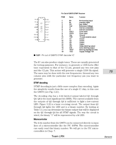
5.21 Pin out of G8870 DTMF decoder IC


                                       The IC can also produce single tones. These are usually generated
                                       for testing purposes. For instance, to generate a 1336-hertz (Hz)
                                       tone equivalent to that of the C2 pin, ground any two row pins
                                       and the C2 pin. This action will generate a single 1336-Hz signal.   75
                                       The same may be done with the row frequencies. Ground any two
                                       column pins with the particular row frequency pin you want to
                                       generate.
                                       DTMF decoding
                                       DTMF decoding is just a little more complex than encoding. Again
                                       the simplicity results from the use of a single IC chip, in this case
                                       the G8870 (see Fig. 5.21).
                                       The decoding chip has a 4-bit latched output labeled Q1 through
                                       Q4. Q4 is the most significant bit (MSB). The current available from
                                       the outputs of Q1 through Q4 is sufficient to light a low-current
                                       LED. Figure 5.22 is a basic receiving circuit. The output from Q1
                                       through Q4 lights the LED and is a binary number. By looking at
                                       Table 5.3, you can determine the binary output that will be displayed
                                       on the Q1 through Q4 for all DTMF signals. The way the circuit is
                                       wired, the binary “1” will be represented by a lit LED.

                                       Microcontroller
                                       The 4-bit number from the G8870 can be connected directly to input
                                       lines of a microcontroller like the PIC 16F84. The microcontroller
                                       can easily read this binary number. We will get to the PIC micro-
                                       controllers in Chap. 7.
                                                       Team LRN                                         Sensors