
Page 119 - Rock Mechanics For Underground Mining
P. 119
BEHAVIOUR OF ISOTROPIC ROCK MATERIAL IN MULTIAXIAL COMPRESSION
c was only 15%. For 2 = 1 , no strength increase was observed (i.e. 1 = c ).
The practical consequence of these results is that, for this rock type, the ‘strength-
ening’ effect of the intermediate principal stress can be neglected so that the uniax-
ial compressive strength, c , should be used as the rock material strength whenever
3 = 0. This slightly conservative conclusion is likely to apply to a wide range of rock
types.
4.4.3 Triaxial compression ( 1 > 2 = 3 )
This test is carried out on cylindrical specimens prepared in the same manner as those
used for uniaxial compression tests. The specimen is placed inside a pressure vessel
(Figures 4.16 and 4.17) and a fluid pressure, 3 , is applied to its surface. A jacket,
Figure 4.16 Elements of a conven-
tional triaxial testing apparatus. usually made of a rubber compound, is used to isolate the specimen from the confining
fluid which is usually oil. The axial stress, 1 , is applied to the specimen via a ram
passing through a bush in the top of the cell and hardened steel end caps. Pore pressure,
u, may be applied or measured through a duct which generally connects with the
specimen through the base of the cell. Axial deformation of the specimen may be most
conveniently monitored by linear variable differential transformers (LVDTs) mounted
inside or outside the cell, but preferably inside. Local axial and circumferential strains
may be measured by electric resistance strain gauges attached to the surface of the
specimen (Figure 4.17).
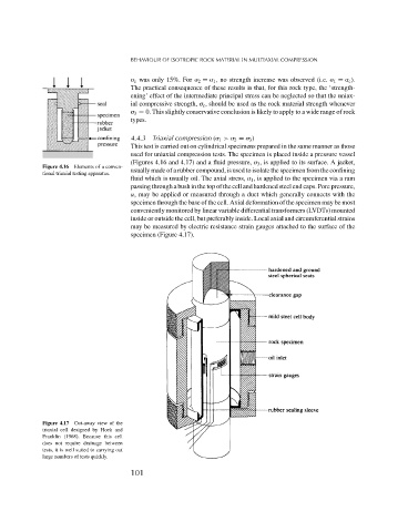
Figure 4.17 Cut-away view of the
triaxial cell designed by Hoek and
Franklin (1968). Because this cell
does not require drainage between
tests, it is well suited to carrying out
large numbers of tests quickly.
101