
Page 128 - Rock Mechanics For Underground Mining
P. 128
ROCK STRENGTH AND DEFORMABILITY
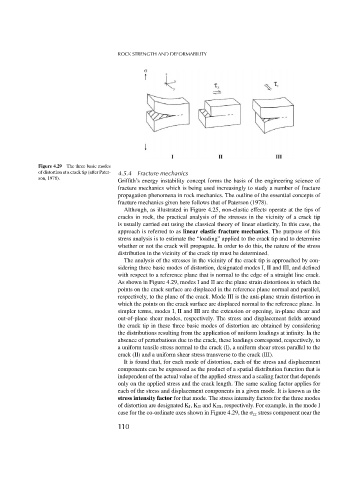
Figure 4.29 The three basic modes
of distortion at a crack tip (after Pater- 4.5.4 Fracture mechanics
son, 1978).
Griffith’s energy instability concept forms the basis of the engineering science of
fracture mechanics which is being used increasingly to study a number of fracture
propagation phenomena in rock mechanics. The outline of the essential concepts of
fracture mechanics given here follows that of Paterson (1978).
Although, as illustrated in Figure 4.25, non-elastic effects operate at the tips of
cracks in rock, the practical analysis of the stresses in the vicinity of a crack tip
is usually carried out using the classical theory of linear elasticity. In this case, the
approach is referred to as linear elastic fracture mechanics. The purpose of this
stress analysis is to estimate the “loading” applied to the crack tip and to determine
whether or not the crack will propagate. In order to do this, the nature of the stress
distribution in the vicinity of the crack tip must be determined.
The analysis of the stresses in the vicinity of the crack tip is approached by con-
sidering three basic modes of distortion, designated modes I, II and III, and defined
with respect to a reference plane that is normal to the edge of a straight line crack.
As shown in Figure 4.29, modes I and II are the plane strain distortions in which the
points on the crack surface are displaced in the reference plane normal and parallel,
respectively, to the plane of the crack. Mode III is the anti-plane strain distortion in
which the points on the crack surface are displaced normal to the reference plane. In
simpler terms, modes I, II and III are the extension or opening, in-plane shear and
out-of-plane shear modes, respectively. The stress and displacement fields around
the crack tip in these three basic modes of distortion are obtained by considering
the distributions resulting from the application of uniform loadings at infinity. In the
absence of perturbations due to the crack, these loadings correspond, respectively, to
a uniform tensile stress normal to the crack (I), a uniform shear stress parallel to the
crack (II) and a uniform shear stress transverse to the crack (III).
It is found that, for each mode of distortion, each of the stress and displacement
components can be expressed as the product of a spatial distribution function that is
independent of the actual value of the applied stress and a scaling factor that depends
only on the applied stress and the crack length. The same scaling factor applies for
each of the stress and displacement components in a given mode. It is known as the
stress intensity factor for that mode. The stress intensity factors for the three modes
of distortion are designated K I ,K II and K III , respectively. For example, in the mode I
case for the co-ordinate axes shown in Figure 4.29, the zz stress component near the
110