
Page 198 - Rock Mechanics For Underground Mining
P. 198
METHODS OF STRESS ANALYSIS
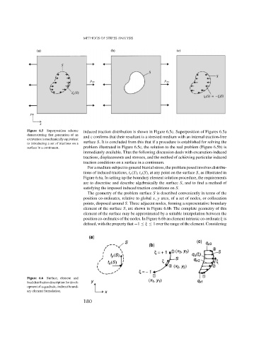
Figure 6.5 Superposition scheme induced traction distribution is shown in Figure 6.5c. Superposition of Figures 6.5a
demonstrating that generation of an and c confirms that their resultant is a stressed medium with an internal traction-free
excavation is mechanically equivalent
to introducing a set of tractions on a surface S. It is concluded from this that if a procedure is established for solving the
surface in a continuum. problem illustrated in Figure 6.5c, the solution to the real problem (Figure 6.5b) is
immediately available. Thus the following discussion deals with excavation-induced
tractions, displacements and stresses, and the method of achieving particular induced
traction conditions on a surface in a continuum.
For a medium subject to general biaxial stress, the problem posed involves distribu-
tions of induced tractions, t x (S), t y (S), at any point on the surface S, as illustrated in
Figure 6.6a. In setting up the boundary element solution procedure, the requirements
are to discretise and describe algebraically the surface S, and to find a method of
satisfying the imposed induced traction conditions on S.
The geometry of the problem surface S is described conveniently in terms of the
position co-ordinates, relative to global x, y axes, of a set of nodes, or collocation
points, disposed around S. Three adjacent nodes, forming a representative boundary
element of the surface S, are shown in Figure 6.6b. The complete geometry of this
element of the surface may be approximated by a suitable interpolation between the
position co-ordinates of the nodes. In Figure 6.6b an element intrinsic co-ordinate is
defined, with the property that −1 ≤ ≤ 1 over the range of the element. Considering
Figure 6.6 Surface, element and
load distribution description for devel-
opment of a quadratic, indirect bound-
ary element formulation.
180