
Page 202 - Rock Mechanics For Underground Mining
P. 202
METHODS OF STRESS ANALYSIS
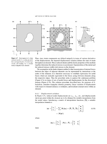
Figure 6.7 Development of a finite Thus, since strain components are defined uniquely in terms of various derivatives
element model of a continuum prob- of the displacements, the imposed displacement variation defines the state of strain
lem, and specification of element ge-
ometry and loading for a constant throughout an element. These induced strains and the elastic properties of the medium
together determine the induced stresses in an element. Superposition of the initial and
strain, triangular finite element.
the induced stresses yields total stresses in the element.
The assumption in the finite element method is that transmission of internal forces
between the edges of adjacent elements can be represented by interactions at the
nodes of the elements. It is therefore necessary to establish expressions for nodal
forces which are statically equivalent to the forces acting between elements along
the respective edges. Thus the procedure seeks to analyse the continuum problem
(Figure 6.7a) in terms of sets of nodal forces and displacements for the discretised
domain (Figure 6.7b). The solution procedure described here, for purposes of il-
lustration, considers triangular element geometry, linear variation of displacement
with respect to element intrinsic co-ordinates, and resultant constant stress within an
element.
6.6.1 Displacement variation
In Figure 6.7c, induced nodal displacements are u xi , u yi , etc., and displacements
[u] at any point within the element are to be obtained by suitable interpolation from
the nodal values. Introducing a matrix of interpolation functions, [N], a suitable
interpolation formula is
⎡ ⎤
u i
u x
[u] = = [N i ][u i ] = [N i , N j , N k ] ⎣ u j ⎦ (6.36)
u y
u k
e
= [N][u ]
where
0
u xi N i
[u i ] = [N i ] = N i =
u yi 0 N i
184