
Page 230 - Rock Mechanics For Underground Mining
P. 230
EXCAVATION DESIGN IN MASSIVE ELASTIC ROCK
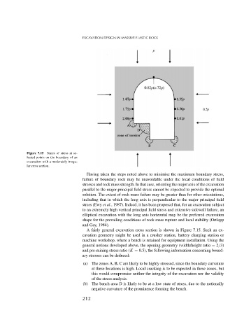
Figure 7.15 States of stress at se-
lected points on the boundary of an
excavation with a moderately irregu-
lar cross section.
Having taken the steps noted above to minimise the maximum boundary stress,
failure of boundary rock may be unavoidable under the local conditions of field
stresses and rock mass strength. In that case, orienting the major axis of the excavation
parallel to the major principal field stress cannot be expected to provide the optimal
solution. The extent of rock mass failure may be greater than for other orientations,
including that in which the long axis is perpendicular to the major principal field
stress (Ewy et al., 1987). Indeed, it has been proposed that, for an excavation subject
to an extremely high vertical principal field stress and extensive sidewall failure, an
elliptical excavation with the long axis horizontal may be the preferred excavation
shape for the prevailing conditions of rock mass rupture and local stability (Ortlepp
and Gay, 1984).
A fairly general excavation cross section is shown in Figure 7.15. Such an ex-
cavation geometry might be used in a crusher station, battery charging station or
machine workshop, where a bench is retained for equipment installation. Using the
general notions developed above, the opening geometry (width/height ratio = 2/3)
and pre-mining stress ratio (K = 0.5), the following information concerning bound-
ary stresses can be deduced:
(a) The zones A, B, C are likely to be highly stressed, since the boundary curvature
at these locations is high. Local cracking is to be expected in these zones, but
this would compromise neither the integrity of the excavation nor the validity
of the stress analysis.
(b) The bench area D is likely to be at a low state of stress, due to the notionally
negative curvature of the prominence forming the bench.
212